Precision Lift System Installation and Atomizer Relocation
Precision Lift System Installation and Atomizer Relocation
Something new for us at Finch of Bookham, we had the incredible opportunity to breakdown and move an Atomizer for a 3D printer headed to the USA. 3D printers with atomizers use a specialised print head design. Rather than heating and pushing filament through an extruder nozzle like fused deposition modelling (FDM), the print material in an atomizer system is supply as liquid polymer solution.
The atomizer itself comprises a small nozzle attached to an ultrasonic transducer vibrating at sky-high frequencies. As the solution flows through, the ultrasonic energy turns it into a cloud of microscopic droplets. This mist gets sprayed onto the print bed in precise patterns to build up the object layer by layer.
Once deposited, the droplets rapidly dry and cure via UV light directed at the print area, solidifying each layer. This process based on inkjet-style dot printing allows tiny droplet sizes under 20 microns, enabling high part details.
Overview
Our team successfully executed a complex lift system installation and relocation of the heavy and large atomizer with its components. The process adhered strictly to manufacturer guidelines, safety protocols, and client specifications. Below is a detailed account of the project phases.
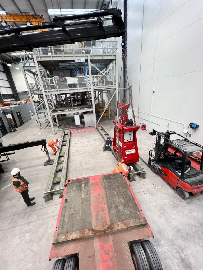
Phase 1: Lift System Installation
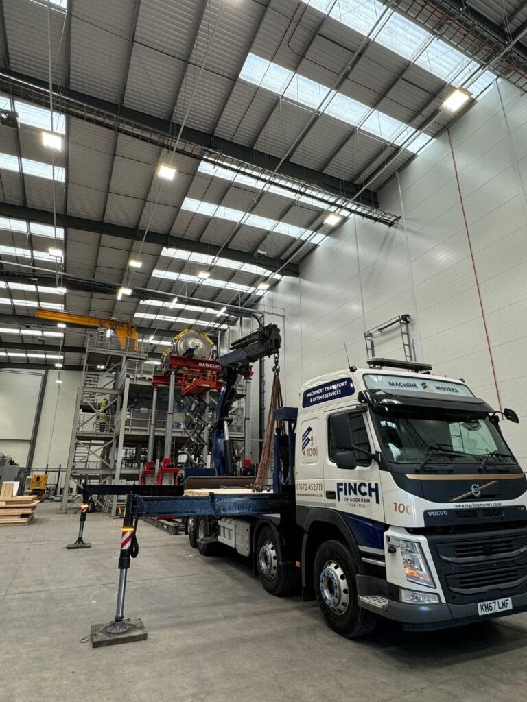
The lorry loader was set up and slings/chains were attached to the Hiab hook, tailored to the slinging arrangement of the load.
The lorry loader hook was positioned over the centre of the lift system component. The slinger securely attached slings from the hook to the lifting points using shackles.
Recognised hand signals were used by the slinger/signaller to guide the Hiab operator during the lift.
After verifying the security of the slinging arrangement, the lorry loader lifted the atomizer from the vehicle bed and lowered it into position. Once the lift system was assembled, electric cables were connected to the site’s power supply.
The process was reversed to safely dismantle the system upon project completion.
Phase 2: Relocating the Melt Chamber to the Platform
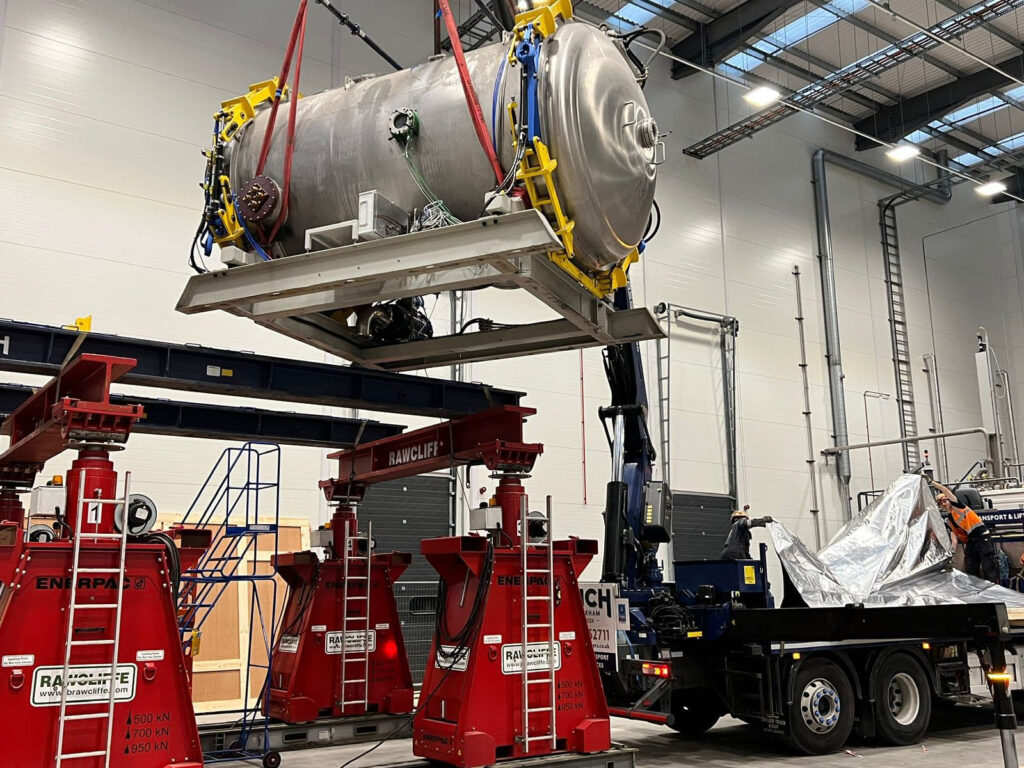
The Melt Chamber of the atomizer was carefully jacked up approximately 300mm to clear the Atom Chamber and then lowered onto machine skates. Using a Tirfor, the chamber was pulled to the front of the mezzanine floor.
Once cleared of the Atom Chamber, the Melt Chamber was lowered another 300mm onto skates. It was then maneuverer over the mezzanine edge until positioned for side-shift lifting. Header beams were installed to lift the Melt Chamber and clear the front skates.
With rear skates still in place, the Melt Chamber was shifted across the header beams. After the rear was positioned over the second pair of side shifts, it was lifted, the skates were removed, and the chamber was lowered onto the second side shifts.
All four side shifts drove the Melt Chamber across the beams until it was safely clear of the mezzanine. The lift system then lowered the Melt Chamber to its minimum height for Hiab transport to floor level.
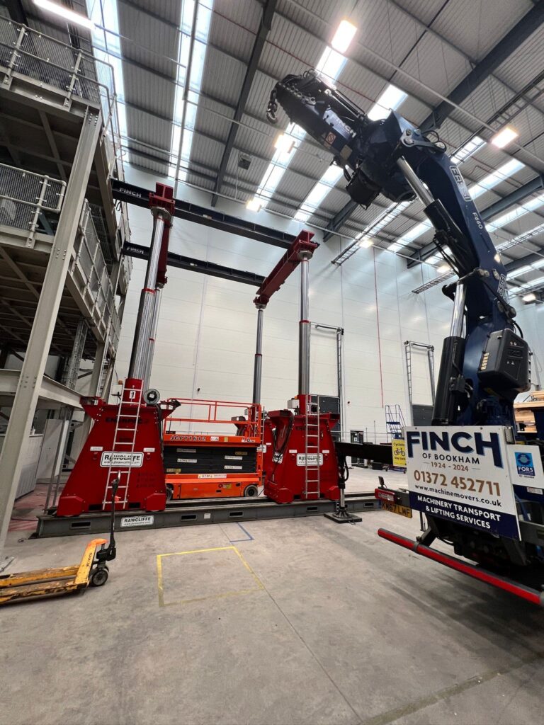

Phase 3: Lifting the Melt Chamber from the Platform
The Hiab vehicle was positioned adjacent to the lift system, with the Melt Chamber within 5.95m of the centre of slew.
The atomizer was slung using spreaders, the Melt Chamber was carefully lifted from the lift system, rotated 180 degrees, and lowered onto a pallet on the vehicle bed.
Phase 4: Lifting Generic Components from the Atomizer
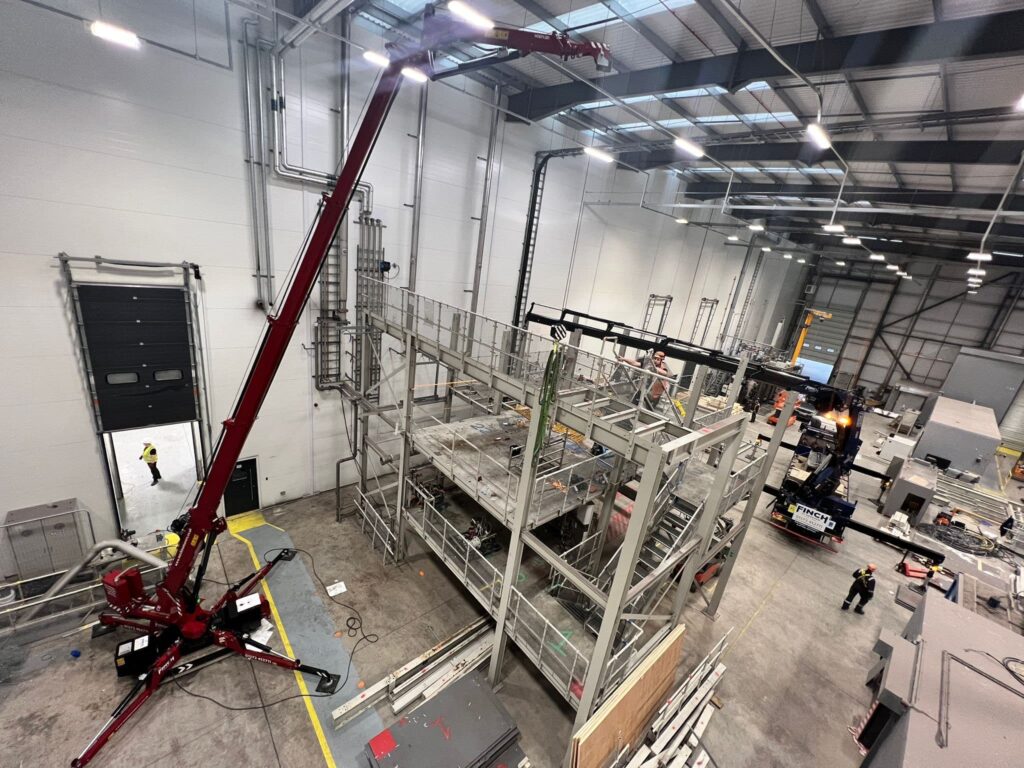
The Hiab vehicle was positioned near the rig, maintaining a safe working radius. Loads were slung with appropriate slings and secured to the hook.
Once the slinging arrangement was confirmed, components were unbolted, lifted from the mezzanine, and lowered to the ground.
This project highlighted our team’s precision and expertise in handling complex lifting operations. Every phase was completed efficiently, ensuring safety, accuracy, and adherence to client requirements.
